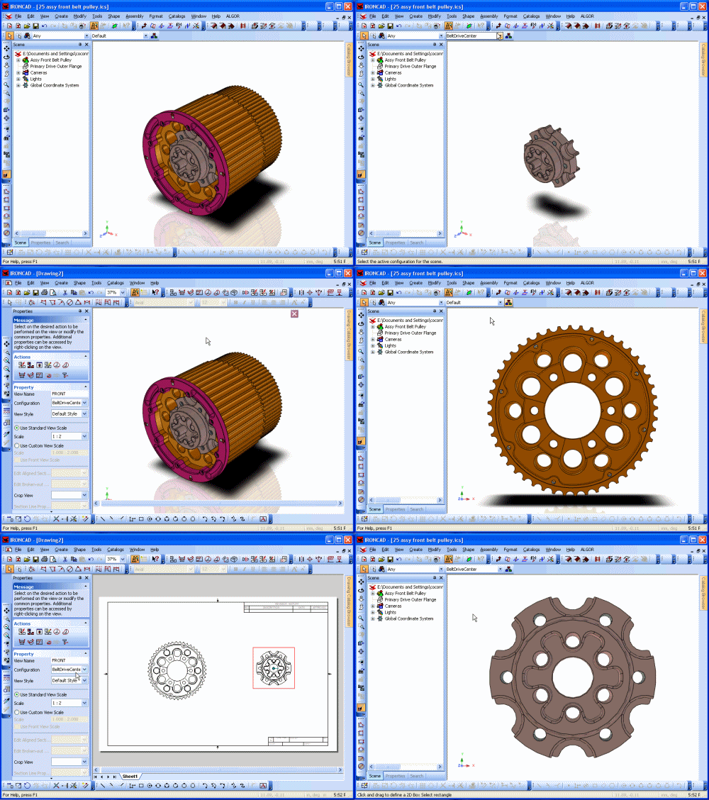
It also allows you to create/insert a new object and insert a Bill of Materials into the drawing.Ĭreate a new drawing view from the following options:Ĭreate a section view displaying a cross-section of a selected standard, general, or auxiliary view.Ĭreate an aligned section view displaying a cross-section of a selected standard, general, or auxiliary view.

With the Create menu, you can create additional sheets or views within a sheet, dimensions, text with leader, GD&T symbols, centerlines/marks, and supplementary sheet geometry and text. Zoom in or out to fit all drawing elements. Zoom in on a selected area of the drawing. Move the view of the sheet to the right/left or up/down. Specify if curve dimensions are to be displayed are hidden. Toggle the display of the Technical Drawing Browser. Toggle the display of the Catalog Browser. Specify if page grid is to be displayed or hidden. Specify if status bar is to be displayed or hidden. Show or hide the 2D Technical Drawing toolbar. Select toolbars to be displayed in drawing environment. This menu provides options for viewing toolbars, sheet grid, status bar, and curve dimensions, as well as options for achieving optimum viewing of drawing components. Set defined symbols that can be used in dialogs.Įdit the properties of the currently selected view.Įdit the properties of the currently selected curve.Įdit the properties of the currently selected curve geometry.Įdit the properties of the cut line style.Įdit the properties of the hatched region.Įdit the properties of the currently selected dimension.Įdit the properties of the currently selected text.Įdit the properties of the currently selected surface texture.Įdit the properties of the currently selected welding symbol.Įdit the properties of the currently selected GD&T symbol.Įdit the properties of the currently selected item bubble.Įdit the properties of the currently selected centerline.Įdit the properties of the currently selected reference curve.Įdit the properties of the currently selected cosmetic thread.Įdit the transferred driving dimensions on the current sheet. Select or create line types used in the drawing. You can also choose to edit an object or scene associated with the drawing, delete a drawing sheet, or edit scene links.Ĭut the current selection and put it on the Clipboard.Ĭopy the current selection and put it on the Clipboard. These include view parameters or annotation information (dimensioning, GD&T symbols, text, hatching, etc.) and the creation and modification of named styles and layers, default element properties, and user-defined symbols. While containing the traditional options such as Undo, Redo, Cut, Copy, Paste, and Delete, this menu also contains additional options for modifying drawing information. Send the current drawing as an electronic file. Import styles and layers from an existing IronCAD drawing. Preview the current drawing prior to printing.

Name and save the contents of the current drawing in a disk file.ĭefine the sheet parameters for the current drawing. Save the contents of the current drawing in a disk file. Sheet Setup is an additional unique option available from the File menu and allows you to define the appearance of your current sheet by choosing either a standard or custom drawing size, displayed in either Landscape or Portrait mode, Display Quality, and defining with documents to use for Linking to Document Properties. In addition to providing options for loading, saving and printing your drawing, this menu also provides options for exporting your drawing into other formats such as. It can be accessed by selecting the "Menu Button" or by activating the Menu Bar (right-click in the application frame background and select Menu Bar or switching the toolbar UI). The drawing menu bar is the location of most of the commands required to create a drawing.


 0 kommentar(er)
